2.0 The Black Box -The Septic System
Domestic wastewater first enters the septic or aerobic tank where the settleable and floatable solids are removed. The water is then either pumped or flows by gravity into an absorption area, elevated sand mound, or other on-lot disposal system. To many individuals the on-lot disposal system appears to be a "blackbox" than magically treats and disposes of wastewater - THIS IS NOT THE CASE !
The on-lot disposal system is in fact an engineered system that is specifically designed, configured, sized and constructed to treat domestic wastewater. Like other engineered systems, the on-lot disposal system requires appropriate location, installation, use, and most important maintenance.
The septic system typically consists of a minimum of two stages. The first is the septic or aerobic tank and the second stage is the soil absorption or recharge area. The septic tank provides for primary treatment of the wastewater, while the soil absorption area provides secondary treatment. Because of the characteristics of domestic wastewater, see Table 1, an improperly sited, designed, or operated systems could result in a potential health risk and adverse impact on the environment.
A septic tank is a water tight chamber that is constructed of durable and corrosion resistant, such as: concrete, plastic, and fiberglass. At one time, metal tanks were used but because of corrosion and rusting these tanks are not a durable or sound tank and need to be replaced. Most residential septic tanks, in Pennsylvania, have a minimum capacity of approximately 1000 gallons. A 1000 gallon capacity is equivalent to a storage capacity of 2.5 days assuming a design flow of 400 gallon per day (gpd).
Note: 400 gpd is the peak design flow for a three bedroom single family residence in Pennsylvania. Therefore, The septic tank does not operate like a holding tank, but provides sufficient detention time to allow the separation of the settleable and floatable solids.
Septic tanks can be either single compartment (Figure 1) or double compartment tanks (Figure 2). Figure 1 is a diagram of a typical septic tank. The tank consists of a durable vessel, inlet and outlet baffles, gas deflection device, inspection ports, and manhole. The inlet baffle force the wastewater down into the tank to prevent short-circuiting of the solids and floatable material across the tank. The outlet baffle inhibit the scum layer, grease, floatable material, and soap scum, from moving out of the tank and into the soil absorption system. Inadequate removal of grease and solids is one of the major causes of on-lot system malfunction.
The gas deflection device is located just below the outlet baffle. The purpose of the gas deflection device is to prevent solids from being carried out of the tank because of decomposition in the sludge blanket. In the sludge blanket, the anaerobic decomposition produces gases which binds to the settled particles causing the solids to rise and flow out of the tank and into the soil adsorption area. The gas deflection device causes the gas bubbles to become dislodged, which causes the particles to settle back to the bottom of the tank.
The inspection ports are used to check the tank and inlet and outlet structures. The manhole provides access to the tank for cleaning and inspection. Table 3 provides a recommended schedule for cleaning of the septic tank, based on the size of the tank and size of the family.
NOTE: Do not ever enter or lean into a partially filled, filled or recently emptied septic tank. The tank may contain hazardous gases or the oxygen concentration of the atmosphere in the tank may be too low.
The renovation capacity and removal efficiency of the septic tank system can be improved through the use of multi-compartment tanks (Figure 2) or my placing multiple septic tanks in series. The PA regulations provide for the use of a maximum of three septic tanks in series.
2.0.1 Septic Tanks
2.0.2 How Septic Tanks Works
The septic tank is not a black box, but a tested and engineered component of an on-lot wastewater disposal system. The main goal of the septic tank is to remove grease, oils, floatable materials, and settleable solids and provide for the partial biological decomposition of the domestic wastewater in an anaerobic (no oxygen) / facultative (low oxygen) environment . In the septic tank, the microbial organisms converts the dissolved and colloidal pollutants into gases, cellular material, and other metabolic end products. In the absence of oxygen, i.e., anaerobic conditions, the wastewater is hydrolyzed and fermented to produce alcohols, organic acids, cellular material, and gases.
The septic tank removes settleable solids and floatable material by holding the wastewater in the tank for a sufficient period of time to permit the solids to separate. A minimum of 24 hours is needed for proper separation and settling. Of the solids, approximately 50% will decompose into the biomass or bio-end products and the remainder settles to the bottom of the tank forming the biological sludge blanket (see Figure 1).
The septic tank provides for primary treatment of the wastewater. The settleable material settles to the bottom of the tank, where anaerobic bacteria break down the organic material. Since grease, oils, and soap scum are difficult to decompose and are lighter, these materials float to the top of the tank between the inlet/outlet baffles forming the scum layer. The general characteristics of the water leaving the septic tank can be
found in Table 4. The septic tank is efficient at the removal of BOD, COD, SS, and grease, but not efficient at the reduction of nutrients, pathogenic organisms, and bacteria. For this reason, an absorption area or some other form of treatment following the septic or aerobic tank is required to further treat the partially treated wastewater. A discharge of partially treated wastewater from a septic tank or aerobic tank, without additional treatment, is not sufficient to adequately protect the public health and quality of the environment.
To maintain the high level of treatment provided by the septic tank and to avoid clogging and overloading of the absorption area, the septic tank requires maintenance. A recommended septic tank pumping schedule is presented in Table 3. The frequency of pumping depends on the number of residents, tanks size, and use of a garbage grinder. The pumping schedule assumes normally daily use and is set as to not permit more than 35 % of the tank to be taken up by the scum layer and sludge blanket. Maintenance of the septic tank DOES NOT include the use of biological or chemical additives. In many cases, the introduction of a bioadditive causes a disruption to the sludge blanket and scum layer and/or can inactivate the beneficial bacteria. This action could then result in the improper decomposition of the wastes or the release of organic material into the absorption area causing the system to become clogged leading to a malfunction. In commercial applications, it may be necessary to add such chemicals because of the nature (such as: high organic loads or grease) of the wastewater.
At a minimum, the on-lot disposal system permitted in Pennsylvania for single family dwellings is designed based on a minimum peak daily flow of 400 gpd or one equivalent dwelling unit. This includes residential structures with 3 bedrooms or less and in some cases it might be advisable to increase the design flow to account for high water use devices, such as: whirlpools tubs. For each additional bed, the peak flow should be increased by 100 gallons.
2.0.3 Septic Tank Sizing
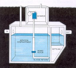
The aerobic tank is an alternative to the conventional septic tank, but it is my professional recommendation that a smaller septic tank should be installed prior to the aerobic tank to provide for an enhanced remove for readily settleable and flotable materials.. The aerobic tank operates like a suspended growth extended aeration system, which is similar to a package wastewater treatment plant. Because of the aerobic (oxygenated environment), the aerobic tank operates at a higher microbial density and higher metabolic rate then a conventional septic tank. Therefore, the aerobic tank results in more rapid and complete breakdown of the wastewater then provided by a septic tank. The aerobic unit produces an effluent with a lower biological oxygen demand (BOD), suspended solids, and fecal coliform concentration then provided by a conventional septic tank. In addition, the aerobic unit provides for nitrification of the wastewater.
Note: Nitrification is the conversion of ammonia and organic nitrogen to nitrite and nitrite.
The aerobic tank uses forced air to maintain the oxygen content of the system at a concentration of at least 2 mg/L. The air is introduced to the system using an air compressor or churning propeller, which provides both oxygen and mixing within the tank. Mixing is critical since it helps maintain the biological solids in contact with the oxygen and the their food source, i.e., the decomposing organic material.
Aerobic systems should be tested and certified prior to use. In Pennsylvania, an aerobic tank must be certified by the National Sanitation Foundation. The NSF is located in Ann Arbor, Michigan. The NSF is a non-profit, non-governmental organization devoted to research and education. Testing of aerobic units is necessary to be sure that the system produces a high quality effluent and that the system has a maintenance and operation manual to minimize system upset and malfunction. Unlike conventional septic systems, aerobic systems are VERY SUSCEPTIBLE to system upset. Aerobic treatment units are vulnerable to shock loading, sludge bulking, homeowner abuse, and mechanical malfunctions. Aerobic units require a constant source of "food" (raw wastewater) and the units should not be turned off. Therefore, it is my professional opinion that aerobic units should not be used in applications that might include: seasonal or vacation homes or weekend retreats.}
2.1 Aerobic Tanks
Grease traps are utilized to remove excessive amount of grease that is typically encountered when land-based disposal is utilized for a commercial and institutional development, i.e., strip malls, motels, cafeterias, restaurants, diners, bars, schools, prisons etc. Improper grease removal can result in clogged lines, clogged inlet and outlet structures, improper renovation within the septic tank, clogging within the drainfield, reducing soil permeability, and failure of the absorption beds. The sole purpose of the grease trap is to remove excess grease before it enters the septic tank or aerobic tank.
Grease traps are flotation chambers that facilitate the separation of the grease and oils from the wastewater. Influents to grease traps typically contain high organic loads that would include: grease, oils, fats, food particles, other suspended particles, and detergents. In many commercial settings, there are smaller grease traps located near the grease producing unit, such as: sink, grill, and dishwasher.
The larger grease trap tank is similar in design to a single or dual compartment septic tank. The larger grease traps should only be connected to grease producing appliances and should not be located after a garbage grinder, because garbage grinders tend to produce very high organic loads which can upset the grease trap. The larger grease traps are usually buried. In the grease trap, the grease floats to the water surface and retained are the tank. Therefore, the primary function of the grease trap tank is to provide for sufficient TIME for the grease to cool and separate from the water. The clarified effluent enters the septic or aerobic tank and mixes with the other wastewater from the facility or source. In some cases, effluent filters are put between the grease trap tank and the rest of the system to limit the amount of grease that leaves the tank, such a filter is manufactured by Zabel Industries.
It is critical that these tanks are level and located to facilitate inspection and cleaning. Since improper grease removal can significantly reduce or cause the failure of the on-lot disposal system, it is highly recommended that a dual compartment tanks be considered. It is recommended that tank be located as close as possible to the source so the wastewater is still hot enough to promote the separation of the grease.
Important message- Grease Traps are a critical component of the system. These units should never be undersized.
2.2 Grease Traps
Calculations Used to Size Grease Traps
(D) * (GL) * (ST) * (HT/2) * (LF) = Size Grease Interceptor (gallons)
D = number of seats in the dining area
GL = gallons of wastewater per meal
ST = storage capacity factor (onsite disposal - 2.5), (normal - 1.7)
HR = Number of hours open (typically 8 to 10 hours)
LF =Loading Factors
1.25 interstate freeways
1.0 other freeways
1.0 recreational areas
0.8 main highways
0.5 other highways
(M) * (GL) * (ST) * (2.5) * (LF) = Size Grease Interceptor (gallons)
M = meals per day
GL = gallons of wastewater per meal
ST = storage capacity factor (onsite disposal - 2.5), (normal - 1.7)
HR = Number of hours open (typically 8 to 10 hours)
LF =Loading Factors
1.25 garbage disposal & dishwater
1.0 without garbage disposal
0.75 without dishwashing
0.5 without dishwashing and garbage disposal
Recommended Minimum Size - 750 gallons
Assuming a 75 seat dining area, an 8 hour per day operation, discharge of 5 gallon per meal, storage capacity factor of 1.7, and loading factor of 0.8, the minimum size of the grease interceptor tank is:
(D) * (GL) * (ST) * (HR/2) * (LF) = Size Grease Interceptor (gallons)
(75) * (5) * (1.7) * (8/2) * (0.8) = 2,040 gallons
We are in the process of setting up Face-to-Face Courses. They will be posted here at our New Training Portal - Training Professionals Online Training Courses. We will be scheduling courses in soil science, soil morphology, hydric soils, and water sampling.
Udemy Featured Courses - 30,000+ Self-Enrichment Courses
Continuing Education for Engineers and Related Professionals (PDH)