2.3 Soil Absorption Areas
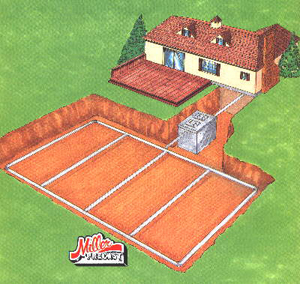
The soil absorption area is an integral component of any conventional and some alternative on-lot wastewater disposal systems in Pennsylvania. The soil absorption system typically receives effluent from a septic or aerobic tank and treats the effluent before the water recharges to the groundwater. For conventional septic soil absorption systems in Pennsylvania, a minimum of 4 feet of suitable material below the system aggregate is needed to properly treat the recharging wastewater. In addition, the key to the long-term success of the system is the proper distribution and pretreatment of the wastewater. Therefore, uneven distribution of the wastewater can cause one area of the system to become overload and ultimately fail. The types of distribution systems include: a distribution box used to split flow equally to individual laterals, distribution loop were the laterals are connected at the end by unperforated piping, and pressurized distribution using a dosing pump or siphon system.
With the exception of a spray irrigation system, the minimum depth to a limiting zone is 20 inches. The actual depth to the limiting zone determines the general suitability of the site and systems that might be permitted in Pennsylvania. A limiting zone is defined as a soil horizon or condition in the soil profile or underlying strata which includes one of the following:
1) A seasonal high water table, whether perched or regional, determined by direct observation of the water table or indicated by soil mottling or redoximorphic features.
2) Rock with open joints, fractures or solution channels, or masses of loose rock fragments, including gravel, with insufficient fine soil to fill the voids between the fragments.
3) A rock formation, other stratum or soil condition which is so slowly permeable that it effectively limits downward passage of effluent. This may include fragipan, duripan or other restrictive horizons.
Open Voids
Conditions,
Perched / Seasonal Water and/or
Fragipan Horizon
Sand and Gravel
Pockets without
sufficient fine material
Types of Septic Systems
In Pennsylvania, the four main types of conventional individual septic systems include:
2.3.1 Conventional Beds and Trench Systems
2.3.3 Elevated Sand Mounds (Title 25. Environmental Protection,
Chapter 73, Section 73.55)
2.3.4 Elevated Sand Trench (Title 25. Environmental Protection,
Chapter 73, Section 73.55)
2.3.1 Conventional Beds and Trench Systems
2.3.1.1 Seepage Beds and Trench Systems
System Highlights (General Highlight of Characteristics Required for this System- It is critical that you review the PADEP regulations and any local agency regulations regarding the siting and use of this system.
1. Where the depth to the top of the limiting zone is 60 inches or greater, the system shall be installed so the bottom of the aggregate is 4 feet above the limiting zone.
2. Maximum Slope of undisturbed soil is 8%.
3. Individual beds of a single on-lot system shall be separated by a minimum distance of 5 feet.
4. Lateral shall be equally spaced or a maximum of 6 feet on center.
5.The bed shall contain a minimum of two lateral or two opposing sets of laterals when pressure distribution is used.
2.3.1.2 Standard Trench (Title 25. Environmental Protection, Chapter 73, Section 73.52)
System Highlights (General Highlight of Characteristics Required for this System- It is critical that you review the PADEP regulations and any local agency regulations regarding the siting and use of this system.
1. Where the depth to the top of the limiting zone is 60 inches or greater, the system shall be installed so the bottom of the aggregate is 4 feet above the limiting zone.
2. Maximum slope of undisturbed soil is 25 %, but for slopes between 15 to 25 % detailed design information is required.
3.There shall be a minimum of two trenches per field.
4. Trenchs shall approximately follow the ground surface contours so that variations in trench depth shall be minimized.
5. There shall be at least 6 feet of soil between the treatment tank or dosing tank and the nearest trench.
6. The width of the bottom of the individual trench shall be 12 to 72 inches.
7. The depth to the bottom of the absorption area shall be 12 to 36 inches.
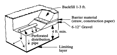
8. The minimum depth of aggregate material under the lateral shall be 6 inches and minimum depth over lateral is 2 inches.
9. Aggregate depth should be uniform.
10. The top of the aggregate material shall be covered with geotextile fabic, untreated building paper, or 2 inch layer of hay, straw, or similar materials to prevent the backfill material from setting into the aggregate.
11. The minimum depth of the earth cover over the aggregate in all installation shall be 12 inches.
2.3.2 Subsurface Sand Filter Beds and Trenches (Title 25. Environmental Protection, Chapter 73, Section 73.54)
System Highlights (General Highlight of Characteristics Required for this System- It is critical that you review the PADEP regulations and any local agency regulations regarding the siting and use of this system. The subsurface sand filter system without an underdrain system is considered a conventional on-lot wastewater disposal system in Pennsylvania. In general, these systems have found application on areas of disturbed or compacted lands, such as mine spoils, overburden stock piles, and compacted surface soils. These systems can be used when:
1. The depth to the limiting zone occurs at less 6 feet below the mineral soil surface.
2. Maximum Slope of undisturbed soil is ?%.
3. The average percolation rate, as determined, by conventional test, see Section 73.15, yields a percolation rate of > 90 min/inch
4.The average percolation rate at a depth between 36 and 60 inches shall be within 3 to 90 minutes/inch.
5. Maximum slope for trench systems is 25 %, but at slopes between 15 and 25 % a detailed design is required. For bed systems, the maximum slope is 8 %.
6. Regarding construction, the system design will meet Section 73.52 (trench) or Section 73.53 (beds) except:
Maximum installation depth is 5 feet.
Minimum depth of approved sand is 12 inch (Section 73.55 (c))
and the sand will meet meet the specifications in Section 73.55(c).
For more details, see Chapter 73, Section 73.54.
2.3.3 Elevated Sand Mounds (Title 25. Environmental Protection, Chapter 73, Section 73.55)
System Highlights (General Highlight of Characteristics Required for this System- It is critical that you review the PADEP regulations and any local agency regulations regarding the siting and use of this system. In general, these systems have found widespread use in Pennsylvania, because of the presence of fragipans, perched water tables, and shallow depths to bedrock and high permeability materials. These systems can be used when:
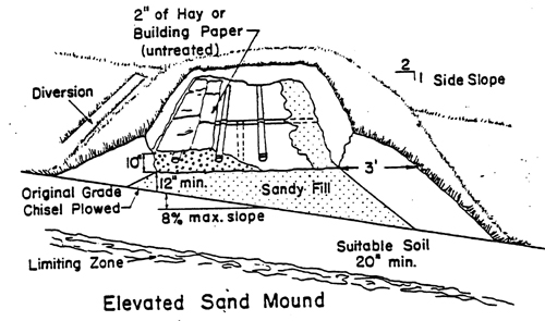
1. The depth to the limiting zone occurs at less 20 inches to less than 60 inches below the mineral soil surface. The system then requires that approved sand be used to create a minimum of 4 feet of satisfactory material between the bottom of the aggregate and the top of the limiting zone, but a 1 foot minimum of sand is required in all elevated sand mound systems.
2. Maximum Slope of undisturbed soil is < 12%, but over 8% the disposal bed would have to meet specific requirements. At over 8% slope, the absorption area shall have a minimum length to width ratio of 4 to 1 with the long axis perpendicular to the slope and upon completion the outside slope of the berm may be no greater than 33.3%.
3. The average percolation rate, as determined, by conventional test, see Section 73.15, yields a percolation rate of 3 to 180 min/inch.
4. The sand will be placed from the upslope side of the bed using lightweight equipment, the slope of the sand not directly beneath the aggregate area shall be approximately 50%, and the top of the sand directly beneath the aggregate shall be level to a tolerance of +2 inches per 100 feet. The bed should be surrounded by suitable berm material and the width of this berm shall be a minimum of 3 feet at the top of the aggregate.
5. Regarding construction, the system design will meet Section 73.53 (beds) with exceptions and additional specifications.
For more details, see Chapter 73, Section 73.55. For large volume disposal beds, there is a special requirements, see Alternative Systems Section.
2.3.4 Elevated Sand Trench (Title 25. Environmental Protection, Chapter 73, Section 73.55)
In-ground version of a trench system. The elevated sand trench system is a high-breed system that is basically an elevated mound with a trench construction.
System Highlights (General Highlight of Characteristics Required for this System- It is critical that you review the PADEP regulations and any local agency regulations regarding the siting and use of this system. In general, these systems have found widespread use in Pennsylvania, because of the presence of fragipans, perched water tables, and shallow depths to bedrock and high permeability materials. These systems can be used when:
1. The depth to the limiting zone occurs at less 20 inches to less than 48 inches below the mineral soil surface. The system then requires that approved sand be used to create a minimum of 4 feet of satisfactory material between the bottom of the aggregate and the top of the limiting zone, but a 1 foot minimum of sand is required in all elevated sand mound systems.
2. Maximum Slope of undisturbed soil for an inground trench is 25%.
3. The average percolation rate, as determined, by conventional test, see Section 73.15, yields a percolation rate of 3 to 180 min/inch.
4. The sand will be placed from the upslope side of the bed using lightweight equipment, the slope of the sand not directly beneath the aggregate area shall be approximately 50%, and the top of the sand directly beneath the aggregate shall be level to a tolerance of +2 inches per 100 feet. The bed should be surrounded by suitable berm material and the width of this berm shall be a minimum of 3 feet at the top of the aggregate.
5. Regarding construction, the system design will meet Section 73.52 (trenches) with exceptions and additional specifications.
6. When a mound system with trenches is used, the area between the individual trenches shall be filled with mineral soil. A minimum distance of 5 feet shall separate sands of individual trenches. This measurement shall be from the toe of the sand.
For more details, see Chapter 73, Section 73.55.
We are in the process of setting up Face-to-Face Courses. They will be posted here at our New Training Portal - Training Professionals Online Training Courses. We will be scheduling courses in soil science, soil morphology, hydric soils, and water sampling.
Udemy Featured Courses - 30,000+ Self-Enrichment Courses
Continuing Education for Engineers and Related Professionals (PDH)